
Description
The DPL Group SBI-145 is a state of the art Craftsperson's test set. It employs the latest and most advanced circuit designs making it possible to combine the following signaling methods in a simple, easy to use "butt set": Touch Tone (TT), Dial Pulse (DP), and Meridian Digital Centrex (MDC*) dialing. MDC is also called Meridian Business Set (MBS*) and Enhanced Business Service (EBS). The SBI-145 does not work on ISDN or other fully digital lines. MDC is used with Nortel M5000 series sets.
The SBI-145 is very light, self contained and line powered. It provides tip and ring identification and audio/visual indication of POTS ringing. Last number redial and a nine number, twenty three digit repertoire memory facilitate dialing. High impedance monitoring, microphone muting, and ground start features are standard and packed in a rugged, easy to use case.
*Registered trademark of Nortel’s Meridian Digital Centrex (DMS-10 and DMS-100)
Intended Use
The SBI-145 is intended for purchase by network providers as a tool to facilitate installing, diagnosing and testing POTS and MDC telephone lines. It is intended to be used by trained service technicians only. Please read and understand the Caution notices stated in the following section before using this unit.
Important Caution Notices (Risk of Electric Shock)
• Phone lines are considered to use hazardous live voltages and currents.
• Normal use of this product involves the connection of the SBI-145 to hazardous live conductors or terminals. These hazardous live voltages may be up to 120 VDC with up to 130 VAC superimposed on the DC component. Do not contact the hazardous live conductors.
• Currents, which can be supplied by, phone lines are greatly in excess of safe levels and caution is advised against contacting either of the hazardous live conductors.
• Before connecting the terminals of the SBI-145, the belt clip should be adjusted so the clip will not touch the user's head or any other part. A rubber stop is employed to prevent this from happening. Do not allow the bolts that hold the belt clip to the unit to loosen.
• Keep well away from the terminals of the SBI-145 while they are connected to a phone line as hazardous live voltages are present. Use caution when connecting and disconnecting to avoid contact with the metal surfaces of the terminals.
• For units equipped with the ground start button, the belt clip must be assumed to be at a hazardous live potential when the red (ring) terminal is connected to a hazardous live voltage. The only isolation employed in the SBI-145 of the belt clip from the red (ring) terminal is the ground start push-button switch. If the SBI-145 has been exposed to a harsh environment the switch may conduct causing a hazardous live voltage to be present at the belt clip. Caution must be taken not to contact the belt clip when the red (ring) terminal is connected to a phone line or other hazardous live source. The yellow and black "Caution" (Exclamation mark, ISO 3864, No. B.3.1) symbol is placed on the SBI-145 unit near the belt clip of this model to alert the user that while the ground start button is pressed the belt clip will be connected to the Ring (RED) lead.
• Ensure all persons in the vicinity of the unit do not contact the belt clip or a risk of electric shock will be present. Remove the terminals from a hazardous live voltage when the operator or bystander may contact the terminals or belt clip.
• The SBI-145 is designed to withstand harsh environments, however, care must be exercised by the user to avoid electric shock due to operation of the unit in damp or other conductive types of conditions.
Always remember to issue ## (on-hook) when a MDC call is complete. The SBI-145 off-hook sequence consists of sending the feature key code and the handset off-hook code. If no ## is sent then the central office assumes the handset is still off-hook and the next call the customer receives will activate the set's buzzer instead of ringing. The customer can still answer the call, and when the handset is replaced the ringing will be enabled for the next incoming call.
Physical Characteristics
1. A non-slip cork backing is provided to facilitate hands free use.
2. The case is made of high impact ABS plastic, a material with a long and successful history of strength and durability in telecom products. It is a two piece case designed for strength, ease of use, and easy maintenance.
3. The controls and keypad have been located to maximize protection from physical damage. They are arranged to allow single handed use when necessary.
4. A spring loaded belt clip is provided. It swivels through a 45° angle for flexible use.
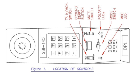
Controls and Indicators
The Talk/Monitor Switch is a slide switch with two positions labeled Talk and Monitor. It is shown in Figure 1, Location of Controls. In the Talk position, dialing can be accomplished as described in the Operation section. In the Monitor position, a high impedance coupling to the line allows audible line monitoring. This may be performed without disrupting the line by placing the Mute switch in the Mute On position. The audible ringer and polarity LEDs are active when in the Monitor position with the Mute switch to the Off position.
The Mode Switch is a slide switch with three positions, Pulse (DP), DTMF (TT), and Centrex (MDC). This switch determines the type of signaling used when dialing a number when the Talk/Monitor switch is in the Talk position.
The Keypad has 12 standard keys. The "*" and “#” keys are used as modifiers to control the internal memory dialing and storage functions. All numeric keys will signal normally unless preceded by the "*" or “#” modifier. To signal either a "*" or "#" in DTMF mode, these keys must be entered twice in succession. The first entry is not signaled or stored. For additional information see the Operation section.
The Mute Switch is a slide switch with two positions, On and Off. The microphone is disabled when the Mute switch is in the On position. The speaker volume is also increased slightly when the Mute switch is on. The POTS line audible ringer and polarity LEDs are disabled when the Mute switch is in the On position. This reduces the amount of noise placed on the line when using the high impedance Monitoring mode. When the Mute switch is in the Off position, an audible confirmation tone will be heard for each dial pad key press. (Dial pad key presses during “press and hold” sequences do not generate confirmation tones.)
The MDC LED lights to indicate audio is present on the MDC line. Therefore, the MDC LED flashes with the alert audio to indicate ringing and stays on to indicate dial tone. Note: This LED only works when in MDC mode.
The Polarity LEDs are red and green. They are enabled when the Talk/Monitor switch is in the Monitor position and the Mute switch is in the Off position. If the red LED is on, the polarity is reversed. If the green one is on, the polarity is correct. The correct polarity is ring to red, and tip to black. These LEDs also indicate power ringing (DTMF and pulse only) when both LEDs are flashing. A warble ringing sound is also heard when power ringing is present and the Mute switch is set to off.
The Ground Start Switch is a push-button switch labeled Ground Start. The belt clip is connected to the ring lead (red) while the button is pushed. This allows a ground start seizure of a trunk by simultaneously touching the belt clip to ground and pushing the button. The Talk/Monitor switch must be in the Talk position, and the mode switch should be in the DP or TT position. Refer to section 1.2 for caution notices regarding the belt clip
The Ground Start Switch is not a standard option and its functionality may be duplicated when dial tone is required from a ground start line by momentarily touching the red (ring) lead to earth ground instead of pressing the ground start button while grounding the belt clip.
Operation
Caution Notices
Refer to the important caution notices in section 1.2 regarding the risk of electric shock while using the SBI-145.
General
Manual dialing and auto dialing can be executed in any order, consecutively or cascaded. The dialer must complete auto dialing the previous entry before another key is entered. Dial pad digits will not be recognized while the device is auto dialing.
New Features
The following items have changed from the previous revision:
1. In the Monitor position, a high impedance coupling to the line allows audible line monitoring. This may be performed without disrupting the line by placing the Mute switch in the Mute On position before connecting to the line to be monitored. The audible ringer and polarity LEDs are active when in the Monitor position with the Mute switch to the Off position. (The transformer used in this coupling has been reinforced to prevent breakage.)
2. Audible confirmation tones are given for each dial pad key press when the Mute switch is in the Off position. (Dial pad key presses during “press and hold” sequences do not generate confirmation tones.)
3. Redial functions for all three dialing modes.
4. Storage of repertoire numbers uses a different sequence and requires that the SBI-145 be in Talk mode and powered while programming. The number of digits is increased to 23. If the storage length has been exceeded error beeps will occur while the digit is pressed. Press # to save the first 23 digits entered.
5. Memory retention is greater than 50 years and no battery is required or used.
6. Fourth column tones may be sent while in TT mode.
7. The MBS II (16 button sets and 22 button add-ons) protocol is supported in both the Address, Key Number and Telco Key Number off-hook formats. An error tone will occur when an incorrect sequence is entered.
8. MDC dial pad keys "*" and "#" may be sent.
9. MDC feature keys, release, hold, off-hook and on-hook may be sent.
10. If an incorrect sequence is entered in MDC mode then three error beeps will occur.
11. MDC current draw is reduced to 15.8 to 20.5 mA.
12. The MDC LED is green in color.
13. The SBI-145 may be configured for the following different options (* is default):
• Set dial pulse speed to 10*, 16 or 20 pulses per second.
• Set dial pulse break make ratio to 3:2* or 2:1.
• Set dial pulse interdigit time to 0.75*, 1.5 or 3.0 seconds.
• Set TT (tone) duration and interdigit time to 51/51, 60/90, 70/70, 80/80, 100/100*, 100/140 or 140/140 msec. for auto dialing.
• Set PABX pause time to 2, 4 or 6* seconds.
• Set MDC code transmission rate to 4, 6*, 8 or 10 per second max.
Pulse Dialing
To use the SBI-145 in pulse mode, set the mode switch to dial pulse (DP) and the Talk/Monitor switch to Talk. When dial tone is heard, dial the number desired. To go on-hook, switch the Talk/Monitor switch to Monitor or remove the clips from the line.
DTMF Dialing
To use the SBI-145 in DTMF mode, set the mode switch to DTMF (TT) and the Talk/Monitor switch to Talk. When dial tone is heard, dial the number desired. To go on-hook, switch the Talk/Monitor switch to Monitor or remove the clips from the line.
MDC (EBS/Centrex) Dialing
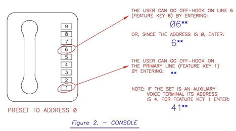
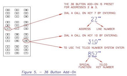
To use the SBI-145 in MDC mode, set the mode switch to MDC and the Talk/Monitor switch to Talk. To send an off-hook signal, enter the following sequence: "Address, Line Number, **". (see also figures 2-5).
Note that an incorrect sequence will not send a signal and an error tone (3 beeps) will occur.
Example 1:
If keys "**" are pressed, an off-hook signal will be sent for the primary line on the primary set, which is address 0, key 1.
Example 2:
If keys "2**" are pressed, an off-hook signal will be sent for feature key 2 associated with address 0.
Example 3:
If keys "21**" are pressed, an off-hook signal will be sent for feature key 1 associated with address 2.
Example 4:
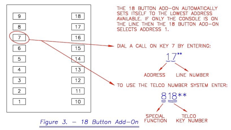
If keys "318**" are pressed, an off-hook signal will be sent for feature key 18 associated with address 3.
Another feature of the SBI-145 allows the user to send off-hook signals without needing to know the address/key system. The alternate system designates buttons with numbers from 1 to 65. This system is referred to as the Telco Key Number system. It is accessed in the SBI-145 by entering '8' followed by the Telco Key Number then **. This 8--** command sends an off-hook to the appropriate line. Primary, 18 and 36 button sets are supported. Refer to tables 1 and 2 for Telco Key Numbers. See figure 3 and 5.
Example 5:
If keys "856**" are pressed, an off-hook signal will be sent for "Telco Key #56", which is feature key 9, address 3.
Note: 20 button add-on Telco key numbers are not supported.
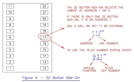
The 16 button sets (M5216 and M5316) have different Telco key mapping than the previous sets which were 12 or less keys. This new system is accessed through the 9--** command. This 9--** command sends an off-hook to the appropriate line. Primary and up to two 22 button add-on sets are supported. Refer to tables 3 and 4 for Telco Key Numbers. See figure 4.
Example 6:
If keys "916**" are pressed, an off-hook signal will be sent for "Telco Key #16", which is feature key 2, address 1.
Caution: MDC lines are not loop current controlled. If a line is left off-hook, it will remain that way until the called party disconnects the call. "##" must be keyed to go on-hook on an MDC line.
Telco Key Number Designations (8--**)
Primary set (address 0) Telco key numbers are numbered 1 - 11.
Table 1 - 18 Button Add-on Telco Key Number Designations
|
Feature Key no. |
Telco Key no. |
Feature Key no. |
Telco Key no. |
Feature Key no. |
Telco Key no. |
|
01 |
12 |
07 |
18 |
13 |
24 |
|
02 |
13 |
08 |
19 |
14 |
25 |
|
03 |
14 |
09 |
20 |
15 |
26 |
|
04 |
15 |
10 |
21 |
16 |
27 |
|
05 |
16 |
11 |
22 |
17 |
28 |
|
06 |
17 |
12 |
23 |
18 |
29 |
The address associated with the above feature keys is '1'. If two 18 button add-ons are used they will be addresses 1 and 2. See table 2, address (2) for Telco key numbers of an 18 button add-on on address 2.
Table 2 - 36 Button Add-on Telco Key Number Designations
|
Feature Key no. |
Telco Key no. |
Feature Key no. |
Telco Key no. |
Feature Key no. |
Telco Key no. |
|
(2) 01 |
30 |
(2) 13 |
42 |
(3) 07 |
54 |
|
(2) 02 |
31 |
(2) 14 |
43 |
(3) 08 |
55 |
|
(2) 03 |
32 |
(2) 15 |
44 |
(3) 09 |
56 |
|
(2) 04 |
33 |
(2) 16 |
45 |
(3) 10 |
57 |
|
(2) 05 |
34 |
(2) 17 |
46 |
(3) 11 |
58 |
|
(2) 06 |
35 |
(2) 18 |
47 |
(3) 12 |
59 |
|
(2) 07 |
36 |
(3) 01 |
48 |
(3) 13 |
60 |
|
(2) 08 |
37 |
(3) 02 |
49 |
(3) 14 |
61 |
|
(2) 09 |
38 |
(3) 03 |
50 |
(3) 15 |
62 |
|
(2) 10 |
39 |
(3) 04 |
51 |
(3) 16 |
63 |
|
(2) 11 |
40 |
(3) 05 |
52 |
(3) 17 |
64 |
|
(2) 12 |
41 |
(3) 06 |
53 |
(3) 18 |
65 |
(2) and (3) represent the address the feature key is associated with.
(Three 18 button add-ons equal one 18 and one 36 button add-on.)
Telco Key Numbers for 16 Button Sets (9--**)
Primary set (address 0) Telco key numbers are numbered 1 - 14.
Table 3 - First 22 Button Add-on Telco Key Number Designations
|
Feature Key no. |
Telco Key no. |
Feature Key no. |
Telco Key no. |
Feature Key no. |
Telco Key no. |
|
01 |
15 |
09 |
23 |
17 |
31 |
|
02 |
16 |
10 |
24 |
18 |
32 |
|
03 |
17 |
11 |
25 |
19 |
33 |
|
04 |
18 |
12 |
26 |
20 |
34 |
|
05 |
19 |
13 |
27 |
21 |
35 |
|
06 |
20 |
14 |
28 |
22 |
36 |
|
07 |
21 |
15 |
29 |
|
|
|
08 |
22 |
16 |
30 |
|
|
The address associated with the above feature keys is '1'. If two 22 button add-ons are used they will be addresses 1 and 2. Note: Only two 22 button add-ons are to be placed on an MDC line.
Table 4 - Second 22 Button Add-on Telco Key Number Designations
|
Feature Key no. |
Telco Key no. |
Feature Key no. |
Telco Key no. |
Feature Key no. |
Telco Key no. |
|
01 |
37 |
09 |
45 |
17 |
53 |
|
02 |
38 |
10 |
46 |
18 |
54 |
|
03 |
39 |
11 |
47 |
19 |
55 |
|
04 |
40 |
12 |
48 |
20 |
56 |
|
05 |
41 |
13 |
49 |
21 |
57 |
|
06 |
42 |
14 |
50 |
22 |
58 |
|
07 |
43 |
15 |
51 |
HOLD |
60 |
|
08 |
44 |
16 |
52 |
|
|
The address associated with the above feature keys is '2', except the 60 code, which is 0
Auto Dialing
The key sequence "*" followed by a digit 1-9, will automatically dial the number sequence stored in the designated memory location.
Storage of Numbers
1. Place the Talk/Monitor switch in the Talk position while connected to a line. Place the Mute switch to Off to hear key press confirmation tones. If the storage operation will take more that 20 seconds or if the dial tone is too loud to hear the confirmation tones then dial another party and use the talk battery while programming. The unit may also be programmed while in MDC mode from a raw 12 to 56 V battery.
2. Enter the “#” followed by the memory location digit (1-9).
3. Enter the number to be stored in memory followed by the "#" key.
4. For example: 452-5232 to be stored in memory location 5: #54525232#
5. Note that a tone will be heard in response to each key press. If 23 digits have been pressed the 24th will cause rapid beeps while the key is pressed. This indicates the key was not stored and that the “#” should be pressed to store the first 23 digits entered.
6. Please note that to store a "*" for signaling purposes the sequence "**" must be entered. This entry will be skipped when auto dialing in pulse dial mode.
7. Fourth column tones, MDC off-hook, MDC feature keys and "#" can not be stored.
8. PABX Pause: A pause is stored in a number sequence by entering the key "*" followed by a key "#" input. When the stored sequence is dialed, the dialer will pause for six (configurable) seconds when it encounters the pause entry. This allows time for a calling card prompt.
Last Number Redial
This is done by entering *0, and is available in all dialing modes. Fourth column tones are sent in TT dialing mode only. “*” and “#” are sent in TT and MDC dialing modes.
Normal Dialing
The "*" and “#” keys are used as modifiers to control repertory functions. All numeric keys will signal normally unless preceded by a modifier. To signal a "*" or "#" in TT mode, these keys must be entered twice in succession. The first entry is not signaled or stored.
Sending Fourth Column Tones in TT Mode
To signal a fourth column tone in TT mode:
1. Press and hold the "*" key.
2. While the "*" key is pressed, press and release “1” for “A”, “2” for “B”, “3” for “C” and “4” for “D”. Note that a confirmation tone is not heard for this key press. (The DTMF signal is sent until the “*” is released.)
3. Release the "*" key.
Dialing "*" or "#" in MDC Mode
To signal a "*" in MDC mode:
1. Press and hold the "*" key.
2. While the "*" key is pressed, press and release the "#" key. Note that a confirmation tone is not heard for the “#” key press.
3. Release the "*" key.
To signal a "#" in MDC mode:
1. Press and hold the "#" key.
2. While the "#" key is pressed, press and release the "*" key. Note that a confirmation tone is not heard for the “*” key press.
3. Release the "#" key.
Pressing Feature Keys and “Hold” in MDC Mode
To signal a feature key in MDC mode:
1. Press and hold the "*" key.
2. While the "*" key is pressed, enter the <address> and <key number> where <address> is 0-7, and where <key number> is 1-22 where applicable. Note that a confirmation tone is not heard for these key presses. An error tone will occur if an incorrect sequence is entered.
3. Release the "*" key. The signal will be sent when the “*” key is released.
To signal a feature key or “Hold” in MDC mode:
1. Press and hold the "*" key.
2. While the "*" key is pressed, enter the <option> and <Telco key number> where <option> is 8 or 9 for regular or 16 button set Telco numbers, and where <Telco key number> is 1-65 where applicable. Use <option> = 9 and <Telco key number> = 60 to send the code for the “Hold” key. Note that a confirmation tone is not heard for these key presses. An error tone will occur if an incorrect sequence is entered.
3. Release the "*" key. The signal will be sent when the “*” key is released.
Configuration Programming
The SBI-145 may be configured for different options as follows:
1. This procedure is similar to the number storage procedure.
2. Place Talk/Monitor switch in Talk position while connected to a line. Place the Mute switch to Off to hear key press confirmation tones. If the storage operation will take more that 20 seconds or if the dial tone is too loud to hear the confirmation tones then dial another party and use the talk battery while programming. The unit may also be programmed when in MDC mode from a raw 12 to 56 V battery.
3. Enter the “#” followed by the "0" digit.
4. Enter the configuration command digits followed by the "#" digit.
5. Note that a tone will be heard in response to each key press.
Description of Configuration Commands
Command Description
01 Set dial pulse speed to 10 pulses per second. (default)
02 Set dial pulse speed to 16 pulses per second.
03 Set dial pulse speed to 20 pulses per second.
04 Set dial pulse make break ratio to 3:2. (default)
05 Set dial pulse make break ration to 2:1.
06 Set dial pulse interdigit time to 0.75 seconds. (default)
07 Set dial pulse interdigit time to 1.5 seconds.
08 Set dial pulse interdigit time to 3.0 seconds.
10 Set TT (tone) duration and interdigit time to 51/51 msec.
11 Set TT (tone) duration and interdigit time to 60/90 msec.
12 Set TT (tone) duration and interdigit time to 70/70 msec.
13 Set TT (tone) duration and interdigit time to 80/80 msec.
14 Set TT (tone) duration and interdigit time to 100/100 msec. (default)
15 Set TT (tone) duration and interdigit time to 100/140 msec.
16 Set TT (tone) duration and interdigit time to 140/140 msec.
17 Set PABX pause time to 2 seconds.
18 Set PABX pause time to 4 seconds.
19 Set PABX pause time to 6 seconds. (default)
20 Set MDC code transmission rate to 4 per second max.
21 Set MDC code transmission rate to 6 per second max. (default)
22 Set MDC code transmission rate to 8 per second max.
23 Set MDC code transmission rate to 10 per second max.
24 Reset SBI-145 configurations only. Beeps indicate completion.
25 Reset SBI-145 configurations and all repertoire memories. Beeps indicate completion.
26 Perform hardware verification of on-board memory. Fast beeps indicate a pass while slow beeps indicate a failure. A successful test will complete in approximately 10
seconds.
Maintenance
To replace the cord or clip, the case can be opened in the following manner:
1. Ensure the SBI-145's terminals are disconnected.
2. With a small screwdriver, pry out the plastic cover with the SBI-145 label. It is located directly above the digits 1, 2 and 3 on the keypad. Remove the two bolts.
3. Pry out the plastic cable fastener on the cord.
4. Remove the two exposed bolts.
5. Remove the two bolts at the top back of the hand set.
6. Open the case and remove the appropriate bolts on the clip or cord.
7. After replacement, reverse the above procedure to reassemble the hand set.
There are no user serviceable parts except the cord and belt clip in the SBI-145.
Technical Specifications
Length: 22.6 cm (8-15/16 in.)
Width: 6.6 cm (2-5/8 in.)
Height: 7.2 cm (2-15/16 in.)
Weight with std cord: 454g (16 oz.)
Case :Yellow or Black hi-impact ABS
Operating temperature range: -20°C to 49°C (-4°F to 120°F)
Storage temperature range: -40°C to 85°C (-40°F to 185°F)
Humidity: 95% noncondensing
Altitude: Less than 2000 m (5486 ft.)
DC and AC parameters" Minimum operating current: 10 mA POTS, 15 mA MDC
Monitor Impedance: 100K ohms (1kHz), typical
MDC Current Draw:
15.8 mA typical, long loop
20.5 mA typical, short loop
POTS current draw:
27 mA typical, long loop
87 mA typical, short loop
Pulse Dialing
Pulse Rate = 10/16/20 PPS, Make:Break = 2:3/1:2
Inter-digit pause = 0.75/1.5/3.0 sec.
|
PPS Setting |
1:2 %Break |
1:2 PPS |
2:3 %Break |
2:3 PPS |
|
10 16 20
|
65.5 typ. 65.1 typ. 63.0 typ. 66.7 Ideal |
10.0 typ. 16.1 typ. 20.0 typ. |
58.8 typ. 60.0 typ. 56.5 typ. 60.0 Ideal |
10.0 typ. 16.7 typ. 20.0 typ. |
DTMF Dialing
DTMF Output Level into 600 ohms:
+0.5 dBm composite signal, typical
+1 dBm maximum, short loop, +4 dBm maximum, long loop
Rate = 3.6 to 10 TPS, Tone frequency error = +/- 1% max.
Minimum transmit duration = 55 msec.
MDC Dialing
(8 kHz) Signaling Output Level into 900 ohms: 1.65 Vp-p, typical
1.35 Vp-p, typical, into line without MDC set
1.0 Vp-p, typical, into line with set
Rate = 4/6/8/10 digits/second
Power Up Pause
550 msec. minimum, 1000 msec. maximum. Set is muted and
receive is limited during power up pause.
Key press confirmation tone 1 kHz, 25 msec. No tone given for “press and hold” keys.
MDC Error Sequence
Silence for 100 msec followed by 1 kHz for 100 msec,
repeated three times.
Mute Switch
A Mute switch is provided which disables
the microphone. The Mute switch also
disables the polarity LEDs, the audible alerter
and the key press confirmation tones.
Memory Dialing
Nine 23 digit numbers can be stored
Last Number Redial
Available for all Talk modes
Memory Retention
Greater than 50 years
Over Current Protection
If the SBI-145 is connected directly to the talk battery
or another non-current limited source, the SBI-145 will
shut down. Disconnect the unit from the source and allow
20 to 40 seconds for a self reset. The over current threshold
is 160mA from a 60 V max. source. (The set may be
programmed from a 12 to 56 V battery while in MDC mode.)
Additional Features
Tip and ring polarity indication
Audible and visual POTS ringing indication. Ringing is 800
and 1000 Hz warbled at a 12.5 Hz rate. No tone is generated
for the first 500 msec. of the ring cycle.
A push button switch is included to connect the belt
clip (held at ground potential) to the ring lead, initiating a
ground start seizure of a trunk.
A MDC LED indicates when any audio is present on the line.
This provides a way for the user to see that dial tone or
ringing is present on the line. Dial tone will make the LED
stay on and ringing will turn it on and off for 2 and 4 seconds
respectively.
No battery is required or used in the unit.
Ordering Information
311-145-c003 Plug cord (SP), 346A Receptacle
311-145-c006 Angled bed of nails cord (ABN)
311-145-c011 Angled bed of nails and RJ-11 receptacle (6”)
c = 0 for yellow and 1 for black
There is no difference in unit performance or construction between different colors.
DPL does not sell mates for the Plug Cord
Warranty and Return
The DPL Group guarantees equipment of its manufacture and each part or component thereof against all defects in material and/or workmanship and agrees to remedy any such defect at no charge provided that the defective unit is returned transportation prepaid to The DPL Group factory from which shipment was made. This warranty extends to the period of one year from the date of purchase. In no case will The DPL Group be liable for any incidental or consequential damages.
This warranty does not extend to products that have been subject to neglect, accident or improper use, nor to units that have been altered by other than The DPL Group authorized personnel.
Return of Equipment: A return of materials authorization number (RMA) must be obtained from The DPL Group before shipping and displayed clearly on the shipping label. For repair information please visit our web site at www.dpl.ca and click “Telecommunications Contacts”.
Notes and Trouble Shooting Hints
1. The SBI-145 does not work on ISDN lines or Norstar Meridian 1.
2. If an invalid off-hook sequence is keyed in MDC mode the SBI-145 will not issue any off-hook code. Three error beeps will occur.
3. Redial on the MDC line functions in the same way as on POTS lines with the following exception: only numbers are stored. Any special function keys are not stored. The redial memory will not be reset if "##" is not used to go on-hook after a call. The redial storage sequence will not start until an MDC line has been placed off-hook by one of the "___**" commands.
4. When using Telco key numbers ensure the phone type is correct when selecting which Telco Key Number table to use.
5. If the SBI-145 will not dial:
• In Monitor mode and Mute Off mode, ensure that one of the polarity LEDs is on. If not, no line voltage exists. Verify a good connection is made with the line.
• In Talk mode, blow in the mic and observe if side tones are heard in the ear piece. If not, the over current protection may be on and the line voltage incorrect.
• All dial pad keys should make noticeable, short confirmation tones in the earpiece with Mute off.
6. If an MDC off-hook cannot be signaled, then try sending the ‘##’ (on-hook) command followed by the off-hook signal.
7. Always remember to issue ## (on-hook) when a MDC call is complete. The SBI-145 off-hook sequence consists of sending the feature key code and the handset off-hook code. If no ## is sent then the central office assumes the handset is still off-hook and the next call the customer receives will activate the set's buzzer instead of ringing. The customer can still answer the call, and when the handset is replaced the ringing will be enabled for the next incoming call.
8. In the case of equipment failure, it must be returned to The DPL Group or a DPL Group authorized repair facility. See section 8 for details.
9. Technical Assistance may be obtained by calling The DPL Group at 1-800-561-8880 between the hours of 7:00 am and 3:30 pm EST. An e-mail may also be sent to techsupport@dplcore.com. Visit www.dpl.ca for more information.
Comments
0 comments
Please sign in to leave a comment.